UTRA ART · Autonomous rover for IGVC
Leading ART's mechanical redesign
Mechanical Subteam Lead · Sep 2026 – present · competition June 2027
For years, ART's mechanical team rebuilt the previous rover, and nobody, from members to project manager, actually owned the mechanical design. In 2026 the rover spent five days at competition and never attempted qualification. This year the mechanical side is being redesigned from a blank page on about $500, and I own all of it: the method every decision goes through, the plan for the year, the team that builds it, and the agreements with the other subteams.
Designing from first principles
Models, a staged plan, load cases, requirements and scoring, in that order.
02 · The teamTeaching the team
The plans double as the syllabus, and every handoff is built so a first-year can succeed.
03 · The roverWorking across subteams
Each platform stage hands embedded and software something they can test on.
Why the reset
Each year's team inherited the rover and patched whatever broke. Parts were picked to be overkill and assumed to work; nobody checked what anything was rated for. Because nobody owned the design, failures were never understood, so they came back.
The old mindset, and this year
| The old mindset | What it cost | This year |
|---|---|---|
| Reuse last year's rover | The motor mount and wheel coupler failed again and again, ate the software team's testing time and ruined wheel-encoder precision | Every part starts from a requirement, on a blank page |
| Go overkill and assume it works | A motor far beyond what the rover needed, and no one checking whether the rest was rated at all | Every part's published rating is checked against a worst-case load case with a safety factor |
| Nobody owns the design | Surface fixes, so the same failures returned every season | One owner for the whole mechanical design, from the models to the parts list |
The hardest constraint: the budget
The budget shapes every decision. Travel and sensors take most of the team's money. What's left is split between embedded and mechanical, which leaves roughly $500 for the entire mechanical rover.
Overkill isn't affordable on $500. Every part has to be the cheapest one that provably passes, which only works if someone owns every requirement behind it. Cost is the top-weighted criterion in every scoring matrix, and parts already in inventory count as free.
01 · The design
Designing from first principles
Every decision runs through the same chain, from the outside world inward. It repeats one level deeper at each step: rover, then drivetrain, then its motor, then the driveline that connects them.
Start from four models
Before anyone talked about parts, we defined the world the rover lives in.
Every decision on this rover, from the stage plan down to a single bearing, comes from these four models. Every requirement, load case and scoring weight traces back to a row in one of them. If a number can't be traced to a model, it doesn't go in.
| Model | What it pins down | Example |
|---|---|---|
| Vehicle | Footprint, mass, required features, life cycle | 3 × 2 ft footprint, ≤ 6 ft tall; mass planned at 30–40 kg (the payload alone is 9.1 kg) |
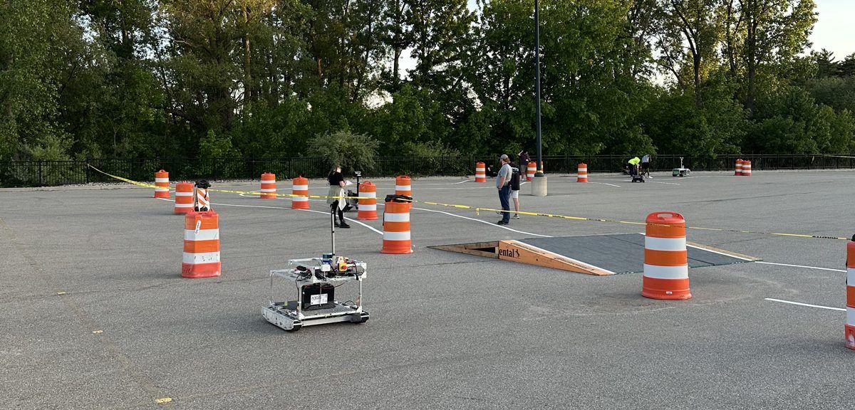
| Course | Length, turns, obstacles, surface, weather | ~500 ft, turns ≥ 5 ft radius, one long 15 % plywood ramp, rain |
| Behaviour | Speed, stopping, manoeuvring, stability, endurance | ≤ 5 mph, > 1 mph average, pivot < 5 ft, never tips, 6 min run |
| Team | Budget, schedule, documentation | ~$500 mechanical budget, competition June 2027 |
Plan the rover in drivable stages
The models set what the finished rover must do. The plan works backward from there in four stages, each one a working platform the next builds on. The stages exist mostly for the other subteams: each ends at a level of drivability where embedded or software can start testing on real hardware, instead of waiting for a finished rover.
| Level | The rover can… | Requires | Subsystems added | Stage |
|---|---|---|---|---|
| 0 | Stand | Balanced ground contact | Frame, wheels | |
| 1 | Roll | Free ground movement | Drivetrain, motors | P.1 Mechanical base |
| 2 | Drive, tethered | Ground movement from electrical power | Drivers, motor circuit | |
| 3 | Drive on its own power | Electrical power generated onboard | Battery, fuses, failsafes | P.2 Electrical platform |
| 4 | Be controlled, tethered | Ground movement from external software input | Drivers, microcontroller | |
| 5 | Be driven remotely | Ground movement under wireless control | Laptop, power distribution | P.3 Software integration |
| 6 | Compete | Every IGVC rule and the full vehicle requirements | Packaging, final assembly, testing | P.4 Final rover |
Each stage is a black box: what goes in, and what must be true when it comes out. Every stage keeps everything the one before it guaranteed, and adds to it.
- Total vehicle weight
- Course conditions
- IGVC rules
- Rolls, carrying worst-case loads with no tipping or slipping
- Known CoG and CoR
- A defined attachment standard
- + electrical power
- + embedded circuits
- Drives on its own power through general worst cases without slipping, tipping or stalling
- Power supply and circuits secured
- + wireless control input
- Driven remotely through full worst cases without slip, tip, stall or losing the operator link
- Every embedded part and sensor secured
- + packaging and the shell
- The final rover: meets every IGVC rule and the full vehicle requirements
- Easy to assemble, tested
Plan each stage down to the parts
Each stage gets a map from its goal to assembled hardware: every requirement document, every decision, every part to buy, every check, and every piece of knowledge the team needs before a step can happen.

P.1 starts from a written goal and its requirements, then splits into four branches that all land before assembly:
Tip and slip conditions bound the centre of gravity and the wheel layout, then get tested on hardware.
Fastener cases → standard requirements → choose a method. One shared way to mount things to the frame.
Requirements from the load cases → select → purchase.
Requirements from loads and stability → type → wheel → specs (scrub, mass, size, material).
The design is verified structurally against the load cases before anything is assembled. Then two drivetrains, the fasteners, the framing and the balance wheels come together, and the stage is tested against the numbers it was designed to.
Find the worst cases, and let them size everything
The course and behaviour models give 13 load cases: every situation the course can put on the rover. Each one sets specific requirements, so no part is sized by guesswork. Numbers are at the 40 kg design mass on the 8.53° ramp.
| Worst case | Load at 40 kg | What it sizes |
|---|---|---|
| Climb the wet ramp | ≈ 66 N of thrust, at wet-plywood grip | Motor torque, traction, wheel material |
| Descend the ramp, speed held | ≈ 50 N of braking | Braking torque back through every driveline part |
| E-stop going down the ramp | ~50 N still pushing it forward | Stopping distance; tipping forward under braking |
| E-stop part-way up the ramp | Hold ≥ 58 N with the power cut | A brake or a drive that can't be back-driven |
| Turn at speed (r = 1.52 m) | Up to ~130 N sideways at 2.24 m/s | Side load on bearings; sliding and tipping in turns |
| Accelerate from rest | ≈ 44 N (0 → 1 mph in 0.5 s) | Peak motor current; meeting the start-speed rule |
| Ramp toe, crest and lip | Vertical impact | Ground clearance; no yield at the lip |
| 6-minute run | Cruise, turns, climb and descent back to back | Heat, battery energy, fatigue life |
| Motor stall | Full stall torque × gearing | No part yields when a wheel jams |
| Wet asphalt, pivoting, lifting, transport | Lower grip, yaw moment, shocks | Traction margin, pivot torque, static strength |
The stability cases feed P.1 directly. The riskiest manoeuvres become tip and slip conditions, which set the allowed range for the centre of gravity and the wheel layout. Those ranges then drive the balance-wheel and framing requirements.
Turn function into pass/fail requirements, then score
Each subsystem gets one sentence for its function. For the drivetrain: "Move the vehicle through the course with its desired behaviour, following team constraints." Each phrase maps to a model, and each produces requirements with a target, a source, a design check and a hardware test: 21 for the drivetrain. Designs that pass all of them are ranked on a weighted matrix that scores only how far they go beyond the requirements.
The drivetrain's top five criteria; eight more share the last 15 points.
The motor came next, selected against the drivetrain's torque and speed requirements and its load cases: a 24 V brushless planetary gearmotor rated 5 N·m at 90 rpm. Its shaft, torque, mass and mounting then became fixed inputs to everything downstream.
One level deeper, the driveline (everything from the motor shaft to the ground) gets the same treatment: "Turn motor torque into motion and carry every load between the ground and the chassis, for the life of the rover, in course conditions." That gives 13 requirements, which become the 10 focused checks members design against (see the team section).
A decision, traced: the driveline
In round one, members submitted four driveline designs. I reviewed each against the 10 focused checks and scored the ones that passed. One example, a compact pillow-block design:
| Check | What the design used | Result |
|---|---|---|
| Wheel rated ≥ 40 kg | Wheel listed at 6 kg max | fail |
| Bearing C, C0 ≥ 800 N | No published rating; member's own estimate ~300 N | fail |
| Torque parts rated ≥ 10 N·m | Pinch-clamp hub and coupler, no rating | fail |
| Steel shaft sized for overhang | 8 mm; the smallest allowed is 13 mm | fail |
| Clearance, sun, turning, parts locked | Met | pass |
It was cheap and light, and it scored 3.22 / 5 on the focused criteria, but it would have broken under the rover's own weight. Round one also exposed a flaw in my own scoring: a fully compliant driveline costs more than the cost scale assumed, so every design was landing at the bottom of it. The cost anchors are being reset so cost can separate good designs again.
Round two kept the selected motor and locked what the reviews settled (a 12.5 N·m flexible coupler, a 6 in wheel rated 40.8 kg, and a hub that fits it) and left members one real choice: a dead axle or a live axle, each with its own sizing rules.
02 · The team
Teaching the team
The mechanical team is mostly first- and second-year students, so teaching is built into the plan rather than done on the side. Every knowledge cloud on a stage map is a lesson that has to exist before the step it feeds. The plans double as the syllabus: by the time a branch reaches a decision, the team has been taught what that decision depends on.
The knowledge the plans call for
Lessons taught so far (driveline design)
For each gap, I learn the topic properly, write the lesson, and teach it at the session where it's needed.
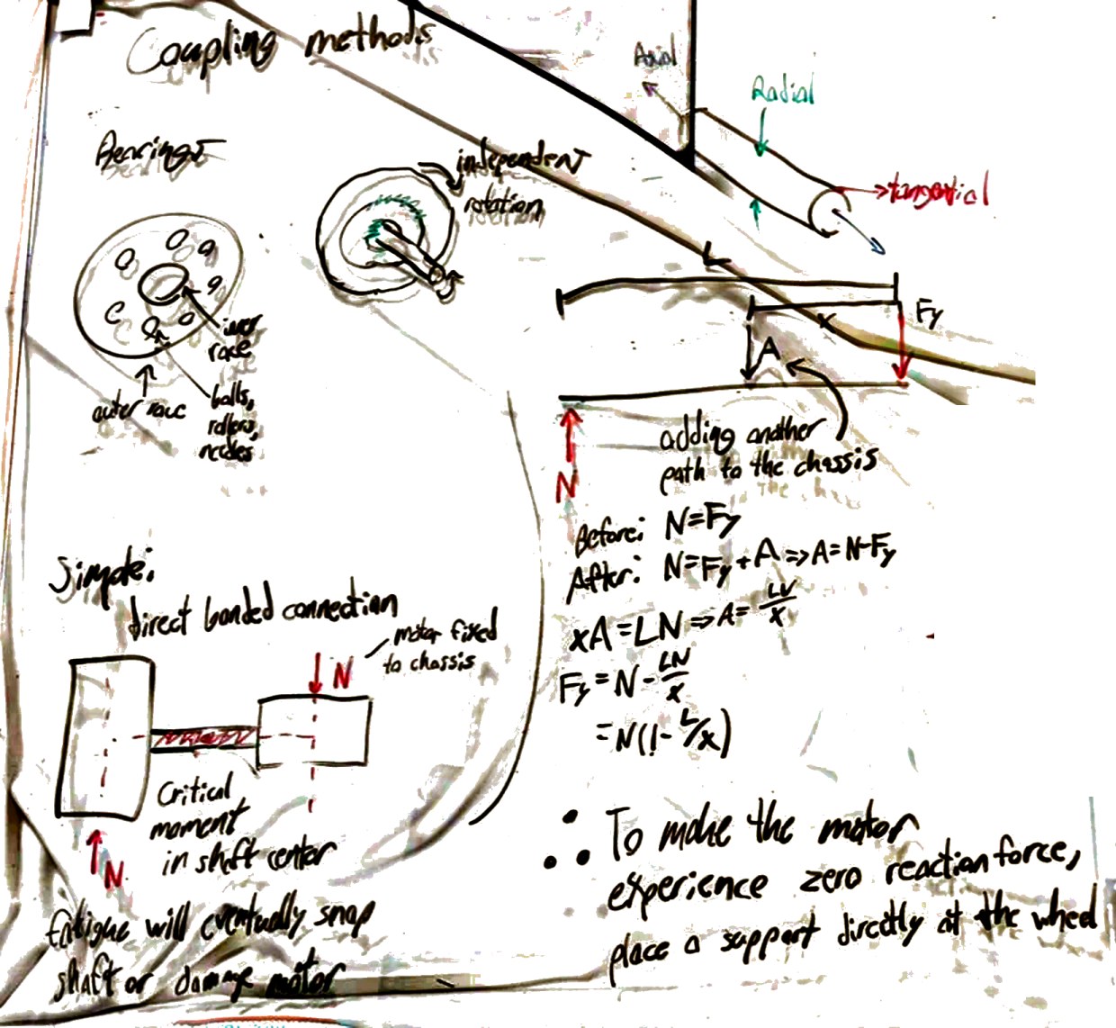
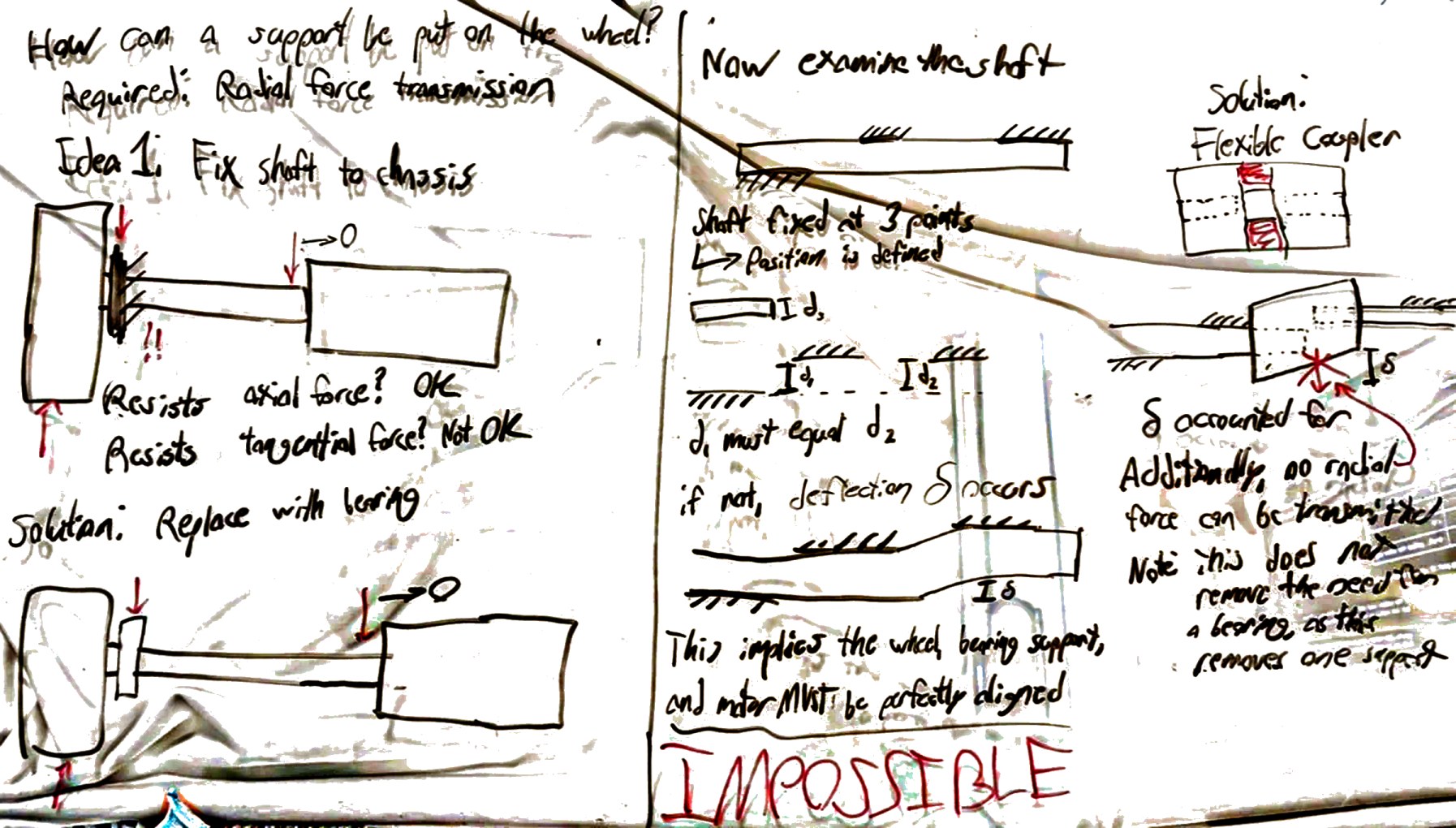
Each lesson is built on a whiteboard first, as a chain of reasoning members can follow rather than a list of rules. These two became the driveline lesson.
Handoffs a first-year can succeed with
The driveline's 13 requirements mostly need hand calculations to check. I turned them into 10 focused checks, each a number off a spec sheet or a measurement in CAD, with the loads and safety factor already built in. Pass all ten and you pass all 13.
That isn't a replacement for understanding. The full requirements sit right next to the checks on the same sheet, and the lessons cover the physics behind them, so members know why their bearing needs C and C0 ≥ 800 N. The checks just keep a first design from getting buried in hand calculations, so their effort goes into the design itself.
The handoff sheet also puts a walking-leg design next to a standard shaft-and-bearing one. If a design meets every requirement and scores well, it doesn't matter what parts it uses, so members should feel free to be creative.
03 · The rover
Working across subteams
In 2026, mechanical problems used up the time software needed for testing. This year the platform stages are built as a contract with the other subteams: each level of drivability is the point where someone else can start testing on real hardware, months before competition instead of days.
What each stage unblocks
| Stage | Mechanical delivers | Which unblocks |
|---|---|---|
| P.1 | A rolling base with known CoG and a defined attachment standard | Every subteam mounts to one standard instead of inventing brackets |
| P.2 | Secured power supply, circuit bay and motor circuit | Embedded tests drivers, power and failsafes on the real rover |
| P.3 | Sensor mounts and a remotely drivable platform | Software tests perception and control on the real rover |
Interfaces, agreed in writing
It works in both directions. Mechanical depends on numbers it doesn't own, so each one is an interface claim that the other subteam's lead signs off. Nothing gets designed around a guess:
| Interface | From | What mechanical gets |
|---|---|---|
| Sensors | Software | Sensor list: mass, size, mount height, field of view, cables |
| Power | Embedded | Battery and electronics bay envelope, E-stop and light parts |
| Motor | Embedded | Motor voltage, current, driver, encoder |
Where it stands
The models are done, the platform is planned in four stages with P.1 mapped to the part level, the drivetrain is defined, required and scored, the motor is selected, and the driveline is defined against it. Member driveline designs are in their second round.